


Extra $8.99 off coupon FNB899, click to copy!
📁 Manuals & FirmwaresDownload
Highlights
✦ Updated USB Tester: FNIRSI FNB58 has a 2.0-inch TFT LCD display, integrated USB-A, Micro-USB, Type-C interface. It is a USB voltage andcurrent detection meter and a mobile communication terminal fast charging trigger with gravity sensor.
✦ Multifunction USB Digital Tester: FNB58 uses external 16-bit ADC, PD protocol physical chip. FNB58 USB tester can monitor the voltage, current, power, resistance, capacity, D+/D- voltage etc, it can be used to test the fast charging protocol of chargers.
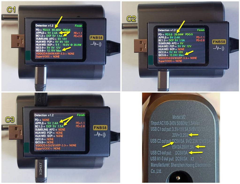
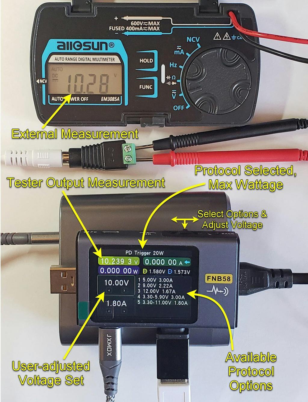
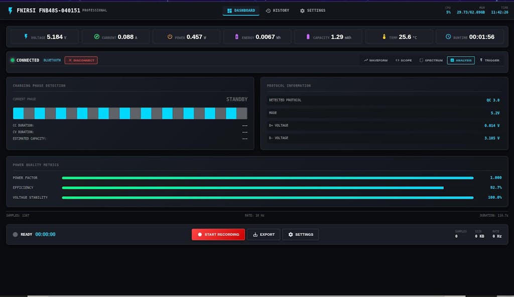
✦ Fast Charge Protocol Trigger Detection: FNB58 supports QC2.0/QC3.0, FCP/SCP, AFC, PD2.0/3.0, VOOC/WARP, Super VOOC 1.0/2.0 trigger. The above protocols all support automatic monitoring. MTK-PE automatic detection. Support QC2.O->PD2.0 protocol conversion.
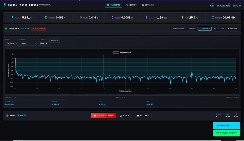
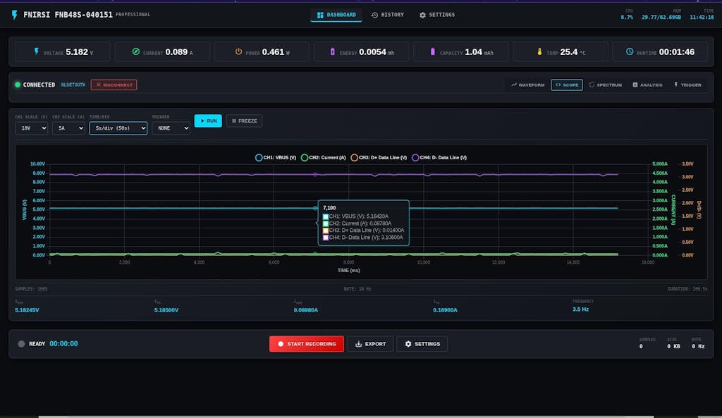
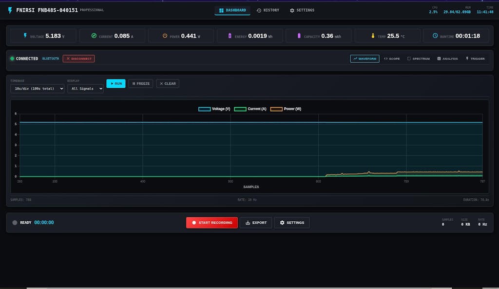
✦ Parameter Recording: The highest six-digit display of voltage, current and power. 10 sets of switchable capacity, power etc. Support low-speed waveform drawing, 2 sps-100 sps sampling rate. Support high-speed ripple drawing, up to 4 M sps sampling rate
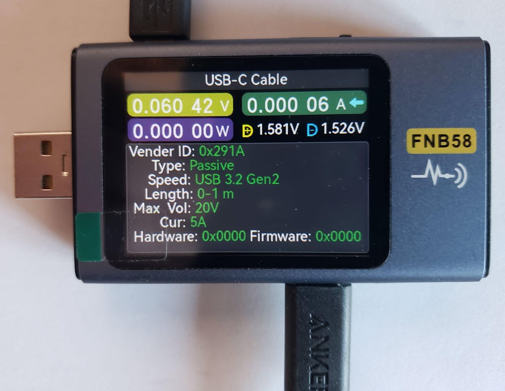
✦ USB tester detection function: The resistance measurement of the wire by the differential pressure method. E-Marker Cable chip reading. DASH Cable data reading. Record of startup time. Onboard temperature measurement. PD monitor. Analog DASH cable.
✦ Note: In order to respond to the environmental protection policy and reduce the use of paper, FNB58 does not come with paper manuals. You can visit the website of FNIRSI on the box to download the manuals, including product update firmware, APP, etc.

The FNB58 USB tester is a high-reliability, high-safety USB voltage andcurrent detection meter and a mobile communication terminal fast chargingtrigger.It has a 2.0-inch full-color ultra-wide viewing angle TFT LCD display, integrated USB-A, Micro-USB, Type-C interface. Use external 16-bit ADC, PD protocol physical chip. It can be used to measure the power supply or power consumption of products such as USB interfaces, mobile phone chargers, and U disks; it can be used to measure the charging power of mobile phones and the input and output of mobile power supplies; it can be used to test the fast charging protocol of chargers.
Specifications
Brand
FNIRSI
Model
FNB58
Monitor Voltage
4~28V
Monitor Current
0~7A
Monitor Power
0~140W
D+/D- Voltage
0~3.3V
Load Equivalent Intemal Resistance
0~9999.9Ω
Equipment Temperature:
°C/°F
Capacity
0~9999.99Ah
Energy Used
0~9999.99Wh
Cable Resistance
0~9999.9Ω
Equipmnt Running Time
99days 23:59:59
Record Time
99days 23:59:59


FNB58 USB tester x1
Using Environment and Precautions
The device should be stored in a soft case, and the operating environment should be at a temperature of -5~40℃, and the relative humidity should not exceed 80%.
The device should be stored in a clean and dry place to avoid moisture, mold, heavy pressure, mechanical damage,humidity and direct sunlight.
Avoid using in the rain or fog, avoid dropping or shocking.
When the screen on the LCD does not light up, it indicates that the voltage is too low, and it needs to be charged in time.
Copyrights
The product specifications are subject to change without notice, allfinal interpretation rights were reserved by FNIRSI Technology Co., Ltd, All trademarks, product images, technical parameters are properties of FNIRSI Technology Co.. Ltd. All rights reserved.
Warranty
30-Day return and refund guarantee (Refer to our Refund Policy), 2-year warranty (only available for orders purchased directly from fnirsi.com), lifetime technique support by FNIRSI.
Please feel free to reach us with any concerns:
Email: service@fnirsi.com / info@fnirsi.com
We strive to reply to you within 24 hours.
FNIRSI has started researching and development manufacturer of quality optical products including Golf rangefinder, laser,measure device and binoculars since 2016.
Focus on the development,researching, and manufacturing for over 8 years.
We are committed to delivering premium products and exceptional customer service, striving to be your most reliable and intelligent assistant.
At Fnirsi, we are committed to providing our customers with the best value for their purchases. To ensure you always get the best price, we offer a 30-day price guarantee on all products purchased directly from fnirsi.com. This policy aims to give you confidence and peace of mind when shopping with us.
What is the 30-Day Price Guarantee?
Our 30-day price guarantee means that if you purchase a product from fnirsi.com and the price of that product drops within 30 days of your purchase date, you are eligible for a refund of the price difference of the products. (Prices are based on USD. No refunds will be given for price changes in other currencies due to exchange rate fluctuations.)
How Does the Price Guarantee Apply?
- Eligibility: The price guarantee applies only to purchases made on fnirsi.com. Products purchased from other retailers or third-party sellers are not eligible.
- Timeframe: The price drop must occur within 30 days of your original purchase date.
- Product Match: The price guarantee applies to the same product (identical model, specifications, and condition).
How to Apply for a Price Difference Refund
If you notice that the price of a product you purchased from fnirsi.com has dropped within 30 days, follow these steps to apply for a refund of the price difference:
- Documentation: Prepare your order number and proof of the price drop (such as a screenshot and link to the product page showing the reduced price).
- Contact Us: Reach out to our customer support team at info@fnirsi.com .Include your order number, proof of the price drop, and a brief explanation of your request.
- Verification: Our team will verify the price drop and your purchase details.
- Refund Process: Once verified, we will process the refund for the price difference to your original method of payment. It typically takes 1-3 business days for you to receive the refund.
At Fnirsi, we strive to provide our customers with high-quality products and exceptional customer service. Our 30-day price guarantee is just one of the ways we ensure you get the best value for your investment. Shop confidently with Fnirsi, knowing that you are always getting the best deal available.
Thank you for choosing Fnirsi. If you have any questions or need further assistance, please do not hesitate to contact our customer support team at info@fnirsi.com.
- Choosing a selection results in a full page refresh.