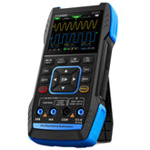
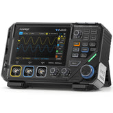
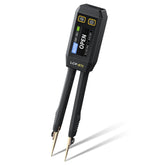
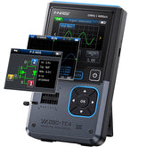
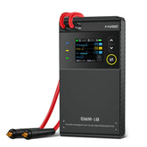
Se hai mai avuto difficoltà a utilizzare la funzione multimetro del tuo dispositivo per testare diodi e continuità, questa guida dettagliata semplificherà il processo. Segui questi passaggi chiari per ottenere risultati accurati ogni volta.
Passo 1: Accedi alla Funzione Multimetro
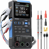
Inizia impostando il tuo dispositivo sulla funzione multimetro. Dopo aver selezionato questa modalità, premi il pulsante di conferma per entrarci. Il dispositivo predefinirà la modalità completamente automatica—questo è il punto di partenza per i test successivi.
Passo 2: Inserisci Correttamente le Sonde
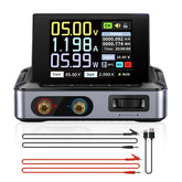
Prendi le sonde del multimetro e inseriscile nelle porte inferiori del dispositivo. È fondamentale assicurarsi che ogni sonda sia posizionata nella presa corretta; un posizionamento errato può portare a letture sbagliate o addirittura danneggiare il dispositivo.
Passo 3: Testa la Continuità in Modalità Completamente Automatica
Testare la continuità in modalità completamente automatica è semplice:
- Collega le due sonde insieme (tocca le punte tra loro).
- Una connessione valida mostrerà zero ohm sullo schermo, indicando che il circuito conduce correttamente l’elettricità.
Passo 4: Limitazione della Modalità Completamente Automatica per i Diodi
La modalità completamente automatica non riesce a identificare accuratamente i diodi. Quando colleghi le sonde a entrambe le estremità di un diodo in questa modalità, il multimetro lo classificherà erroneamente come un resistore ad alta resistenza invece che come un diodo. Per testare correttamente i diodi, devi cambiare modalità.
Passo 5: Passa alla Modalità Continuità Diodo
Individua la manopola di selezione della gamma sul pannello del dispositivo. Ruota la manopola per passare dalla modalità completamente automatica alla modalità continuità diodo—un’impostazione progettata specificamente per il rilevamento dei diodi e per un test di continuità migliorato.
Passo 6: Riprova la Continuità in Modalità Continuità Diodo
Una volta in modalità continuità diodo, riprova la continuità per notare il miglioramento:
- Ricollega le due sonde tra loro.
- Questa volta, lo schermo indicherà la conduzione e emetterà un suono (la nota “modalità buzzer”). Il buzzer fornisce un segnale acustico, così non devi monitorare costantemente lo schermo.
Passo 7: Testa un Diodo in Modo Accurato
Per testare correttamente un diodo, segui questi sotto-passaggi:
- Identifica la polarità del diodo: Cerca la striscia bianca su un’estremità—indica il catodo (terminale negativo).
- Collega le sonde: Attacca la sonda nera all’estremità con la striscia (catodo) e la sonda rossa all’altra estremità (anodo, terminale positivo).
- Controlla la lettura: Quando un diodo funzionante è collegato correttamente, lo schermo mostrerà la corrispondente caduta di tensione diretta. Questo valore indica direttamente che il diodo è in grado di condurre, segnalando che il suo funzionamento è normale.


